How to connect Internal System Cables
As with power cables, it may be necessary sometimes to adjust or reconnect some of the internal connections, either for troubleshooting or for adding new hardware. Some of these connections can include but are not limited to: internal USB 2.0 and USB 3.0, Front Panel Audio (sometimes called HD Audio), RGB cables, fan connectors (3 and 4 pins), front LED connectors, case speaker, and Thunderbolt connector. Plugging each of these in is fairly simple; the hardest part can be getting to them, depending on the case.
Fan Connectors
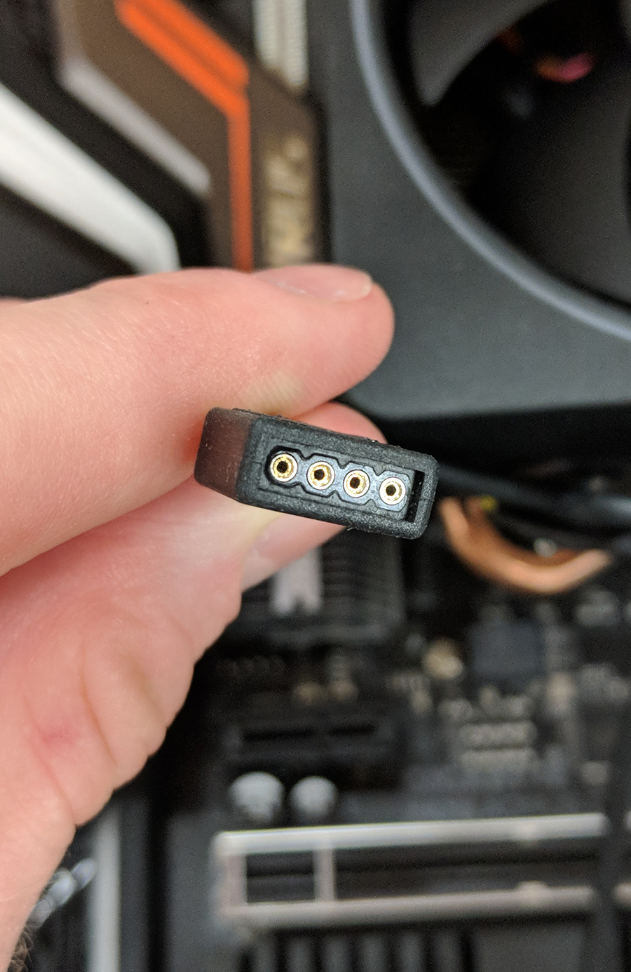
Since most fans have bearings, they do eventually go bad and start to make noise. This is especially true of top fans, since gravity adds to the stress on the bearings. If you suspect that one of your fans may be going bad, give our support team a call so they can help isolate the problem. Fan connectors come in either 3-pin or 4-pin configurations. Most motherboards will have 4 pin headers you can use with either 3 or 4-pin, although some boards do have 3-pin only headers, though this is very uncommon. When looking at the header on the board, you will see a vertical piece of plastic on one side that’s slightly off center. That tells which way to plug in the fan connector. On the fan connector, there are two ridges that will line up with the plastic guide on the header. It is possible to still plug it in incorrectly if you force it, so be careful.
A few things to note about fans before we move on. CPU cooling fans should ALWAYS be plugged into the header that is specifically labeled “CPU Fan” and not “CPU Optional” or any other header. Sometimes these headers are white, but this is not always true. The reason for this is that the CPU fan header reads temperatures directly from the CPU and scales the fan speed accordingly. On top of that, if there is nothing plugged into the CPU fan header then the system will give you a POST error each time you boot it up. Also, if you have an all in one (AIO) liquid cooler, also only plug that into the CPU fan header. Some boards will have a fan header dedicated for a water pump (labeled W_PUMP), this is intended for a dedicated water pump and not an AIO unit. The last thing to note about fans is to avoid using fan headers that are labeled “W_PUMP”, “H_AMP”, or M.2_FAN.” These are meant to power different kinds of fans than normal case fans, and using them can make your fans much louder, even after changing the fan profiles in the BIOS. Whenever possible, use fan headers labeled either “SYS_FAN” or “CHA_FAN.”

Front Panel Audio
The Front Panel Audio connector allows the onboard audio chip to use the top (or front, depending on case) headphone and microphone jack.
Note: that the NX and Small Block cases do not have these, so this guide will not apply to them.
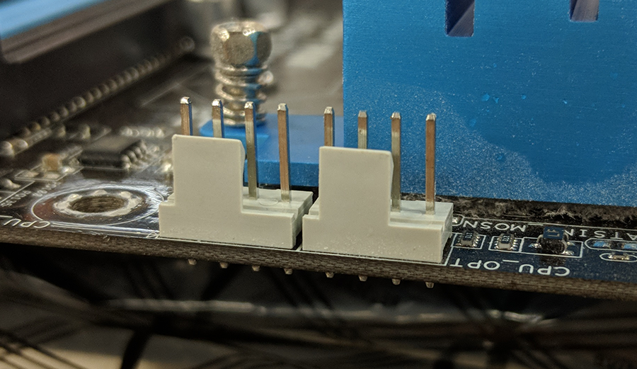
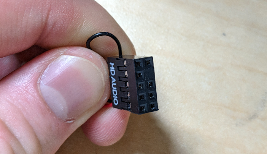
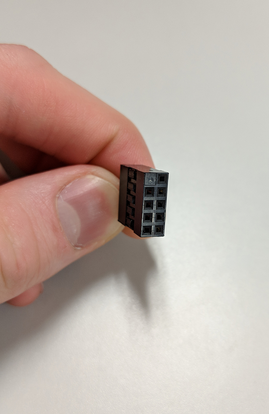
The cable for front audio is very long since the pins for it are usually in the very bottom left corner of the motherboard. The pins themselves are arranged in two rows, one on top of the other, and may be labeled either “AAFP” or “HD Audio.” On most boards, the bottom row has 5 pins and the top row has 4 with a gap between them. Some boards may reverse this, so always double check to confirm this. Now, if you look at the Front Audio connector, you will see holes that line up perfectly with these pins. Pay close attention to the one pin hole that is filled in; that one needs to line up with the empty spot in the pins. Once you’ve determined the proper way to plug it in, press the connector carefully into the pins. Make sure to not bend or angle it too much as the pins can be bent fairly easily.
Internal USB cables
Even though they are identical in terms of speed and performance, internal USB cables connect in very different ways. USB 2.0 internal connections use either a 9-pin connector or a 5-pin connector directly to the motherboard. Why two different types for USB 2.0? It depends on the device, but if a device uses a 9-pin connector it’s because it needs the additional bandwidth provided by the extra 4 pins. The 9-pin connector is arranged in two rows, one on top of the other with the last pin one row being empty on the board and on the connector. These need to line up when plugging in. The 5-pin standard is less common these days but may still be used for some devices. If you have an older Velocity Micro system with an older case design (GX2, MX2, LXE, etc.), the multi-card reader uses this type of connector. The 5-pin connection is a single row of pins rather than two and has the added benefit of being able to connect two of these into 1 USB header. One thing to note when plugging these in is that the red colored cable should be on the side opposite of the empty spot (this spot is sometimes referred to as the “dead pin”). Most boards have at least two USB 2.0 headers, whereas some have only one or as many as three or more. Check your motherboard’s manual if you are unsure of how many you have or where they are.
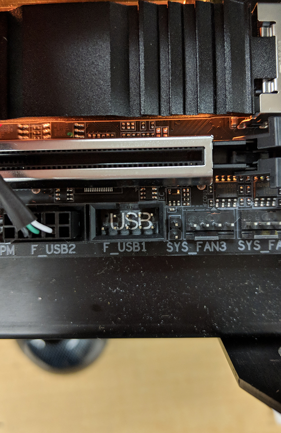
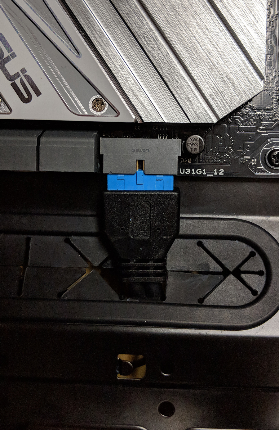
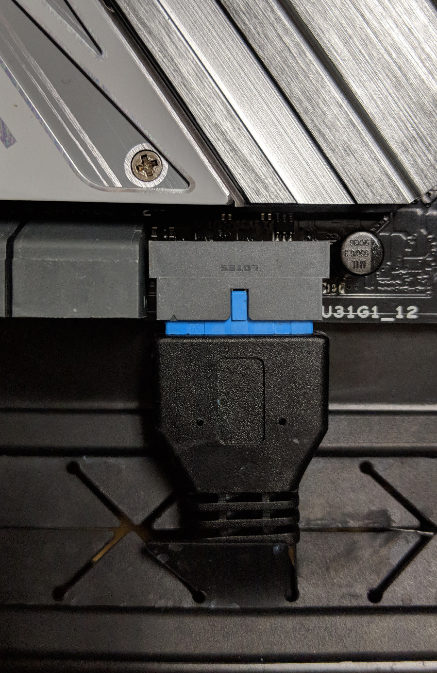
Next is USB 3.0. USB 3.0 internal cables are more straightforward, with only a single type and easily plugged in. They are easier to spot since they are larger, but different manufacturers put them in different places. The most common places are along the right edge of the board (usually between the ATX 24-pin and the SATA ports) or along the bottom edge of the board (next to or near the USB 2.0 headers). It’s also worth pointing out the two different ways they can be connected. The older and more traditional way was to have the pins sticking out vertically from the board, essentially the same as any other header on the board. But newer boards have one or both headers with the pins pointing outwards from the board. For example, if the USB 3.0 header is on the right edge of the board, then the header will be facing to the right. In either case, if you look at the connector on the board you will see a rectangular cutout in the plastic. This lines up with a notch on the connector to help you plug it in correctly. Make sure you line up the notch and cutout correctly, as it’s possible to bend the pins in the header.
RGB headers and cables
This can be a little confusing, since different manufacturers implement the RGB standard in their own way. The default pin arrangement for a header is 4 pins, one for Red, Green, and Blue respectively, plus one for 12V power. However, a manufacturer like Asus, for example, has their layout as Green, Blue, and Red. This won’t matter much if you are using RGB accessories from one manufacturer, but it can get confusing when you try to mix and match different manufacturers. Unless you are adding more RGB accessories to your Velocity Micro system, you shouldn’t need to worry about this.
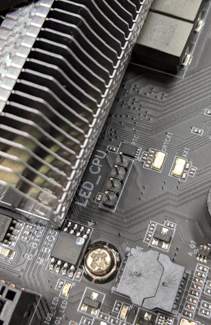
You are most likely to need this guide if you have an AMD Ryzen-based computer from Velocity Micro. AMD’s Wraith cooler has an RGB ring around the fan, which can be controlled through the RGB connection. As with USB connections described earlier, there can as few as one or as many as three or four on a single board. For the most part, these RGB headers are white, but this is not always true, so check your motherboard’s manual if you aren’t sure. They are most commonly placed along the bottom edge of the board, along the top right edge, or above the top PCIe slot. Fortunately, RGB cables are fairly easy to connect, with just a 4-pin header on the board. There is one thing to keep in mind, however. On the RGB connector cable, there will be an arrow on both sides that will correspond to a certain pin on the header, called “Pin 1”. Unfortunately, most manufacturers don’t label this very well on the board, so you will probably need to check the motherboard’s manual for help. It is important that you correctly plug it into pin 1, or your RBG accessories will not synchronize with each other.
Front LED and power cables
These can be difficult mainly because the connectors and headers are very small and may be difficult to reach. The standard arrangement of front power connectors includes an HDD LED, Power LED (on separate positive and negative connectors and pins), a Power Switch connector, and a case speaker connector. Some cases may have an additional connector for a reset button (common on older Velocity Micro cases) or lack the HDD LED (also on older Velocity Micro systems as well as the VX case). As a general rule, the front panel header is almost always in the bottom right corner of the motherboard below the SATA connectors, but there are exceptions. Another general rule is the layout of the header itself, which is usually two rows of pins. Most manufacturers adhere to the same standard of, in order of left to right: HDD LED in the first two pins on the bottom row, Power LED positive in the first pin on the top row, Power LED negative in the pin immediately next to that, Power Switch immediately next to Power LED negative, and Reset Switch immediately below Power Switch. The case speaker connector will take four pins on the top row all the way to the right. One thing to note about the case speaker is to watch out for is the number of pins on the top row. If there are only four pins, then you can simply plug the case speaker into those and move on. But if there are five pins, you need to leave the last one on the right unused by the case speaker. That last pin is for Chassis Intrusion Detection (CID), but Velocity Micro cases do not use this feature. As stated earlier, there are exceptions to this layout. Some boards have a gap between Power LED positive and negative, for example. If you are unsure of what your layout is, you can always check the motherboard’s manual.
Thunderbolt card
Thunderbolt cables have a 5-pin connector on one end and a 9-pin on the other. The 5-pin part goes into the motherboard in a distinctly shaped connector. The 5-pin part also has a plastic latch that holds it in place. You will need to release this latch to unplug it from the board if required. The other end of the cable is the 9-pin. It looks similar to an internal USB or front panel audio; however, the dead pin is in a different position. Make sure to line it up correctly or you will risk bending the pins. Just like RGB connectors, Thunderbolt is fairly straightforward.